A cautionary tale of how something apparently simple can catch you out if you get over-confident and fail to pay careful attention to what you’re doing.

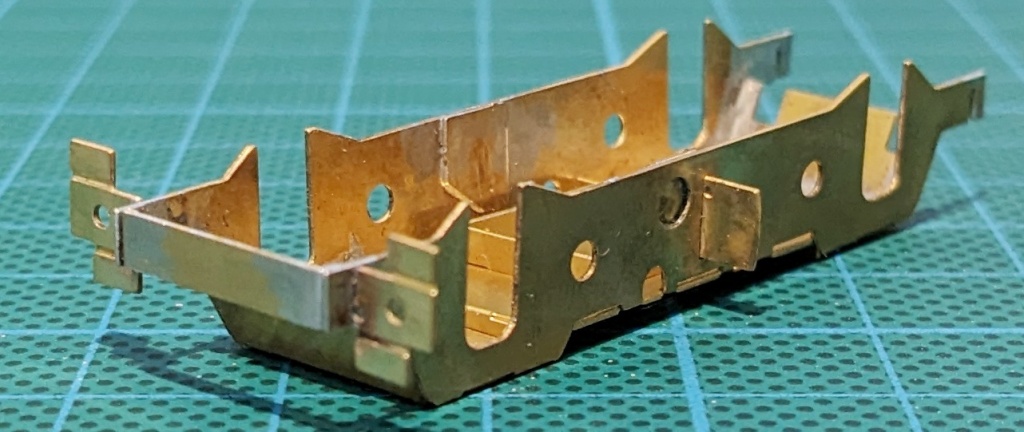
Fresh from successfully putting together the bearing carriers from the Penbits sprung bogies kit, I was looking forward to what promised to be some simple folding and soldering to assemble the subframes. Indeed, to begin with, all went as expected: the main subframe part for each bogie just needs four simple folds to get it into the correct shape. A little care getting the angles right and judicious use of my “hold and fold” tool and a pair of pliers made short work of that task.
Before moving on, I did a little housekeeping job suggested in the instructions and made sure that all the 0.5mm diameter holes in the various subframe parts on the fret were opened up properly by running a drill bit through them. The next step was to add the inner and outer end stretchers. Again this should be a simple job but I suspect that over-confidence struck. I folded up both parts for the first bogie and test fitted them to the subframe concentrating on getting them at the correct end. So, yes, I got the inner stretcher at the correct end but I somehow managed to solder it the wrong way round! At least that problem was resolvable – if annoying – a hot soldering iron can unsolder as well as solder. While that was a bit messy, I managed to correct my error.
The outer stretcher was not so kind to me – or perhaps it’s fairer to say I was not so kind to it! I should probably have taken a break after making that first mistake but I pressed on. I found the outer stretcher was being a tad awkward to get in place and keep there ready for soldering. Let’s be clear: that was entirely my fault because the kit is well designed and there are perfect slots in the parts for this. No, it was a case of butterfingers Martin and while trying to line the outer stretcher up with the slots for it in the subframe, I dropped it and managed to break off the leg at one end! I took that as a sign from the modelling gods and stopped for the day.
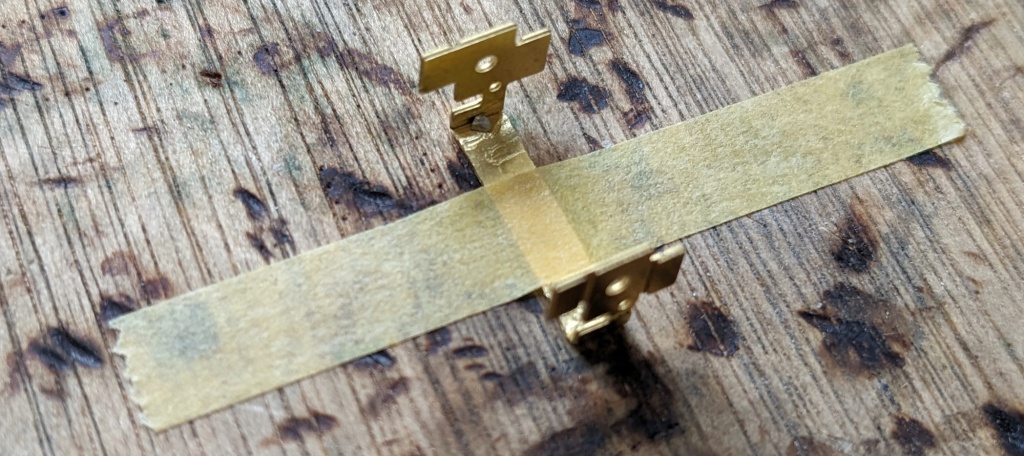
I should mention at this point that each stretcher involves two pairs of folds (which was fine) and the instructions tell you to strengthen the first pair of folds before making the second pair of folds. This wasn’t the cause of my problem because I did follow that instruction but from now on I was super sensitive to these delicate parts and my previous clumsiness. So out came the trusty masking tape to hold each one securely to the work surface while I added a strengthening dose of solder to the folds.
Some time later…
Rested and recovered, I switched to the second subframe. Thankfully, this time, things went to plan including adding the outer stretcher detailing part. I moved on to the quaintly named traction ears. These simple parts just need one fold and soldering in place but I had to make sure I got each one orientated correctly on the right side of the subframe. The instructions suggest that you use the large hole in the subframe as an access point to add flux and solder but I didn’t get on with that approach. Instead I used my usual technique and fluxed the part from the inside of the subframe, added a chip of solder and zapped it with the hot iron.
The last things to do were to fit the secondary spring seats to the undertray and then add that to the subframe assembly. The instructions provide a sequence of four photographs which, if followed, help to get the undertray the right way up and the right way round (though I believe the latter doesn’t actually matter).

Having finished the second subframe, I resumed work on the first one to get it completed as far as possible. I went back to the broken outer stretcher to see if anything could be done to fix it. Some email correspondence with Ian Penberth had given me a couple of ideas to try but, ultimately, I concluded that the fact that the break was at one of the tiny folds meant that any repair would be prone to a future failure – not least because it was so close to a load-bearing hole that takes one end of the suspension wire. I decided that the only option was to order a second kit and cannibalise it for a replacement part (at least that way I would have a ready supply of more spare parts for any other disasters during the rest of the project).
At least I can say, with a degree of irony, that I’m well on the way to fulfilling one of my project objectives – i.e. to learn all the ins and outs of this Penbits sprung bogies kit! Galling as it might initially feel, there’s no better way to learn than by making mistakes and I certainly made a couple here. First, I rushed ahead too confidently; second I didn’t treat the apparently simple but actually fiddly inner and outer stretcher parts with sufficient respect. That led me to initially fit one the wrong way round and then compound the error by breaking another one. On top of that, I strayed away from my tried and trusted technique for soldering small parts. I usually find a way to temporarily secure them in place then add the flux and small chip of solder before applying the hot iron to the joint. I think experimenting with a slightly different approach was unwise and led to less neat results. But I got there in the end!
When the second kit arrives (Ian Penberth tells me it’ll be a little while because he’s out of stock at present) I’ll be able to steal the outer stretcher from it and finish the first subframe. In the meantime, I’ll pause for some reflection and then steadily work on the bolsters.
