While I wait for a second Penbits kit to provide a source of spare parts, I’ve moved on to the next stage in building the sprung bogies.
After a short break, it’s time to continue. The Penbits kit employs a bolster for each bogie designed to serve two purposes. First it provides the means of fixing the bogies to the pivot points on the Bachmann locomotive’s chassis; second, it provides the method of secondary suspension.
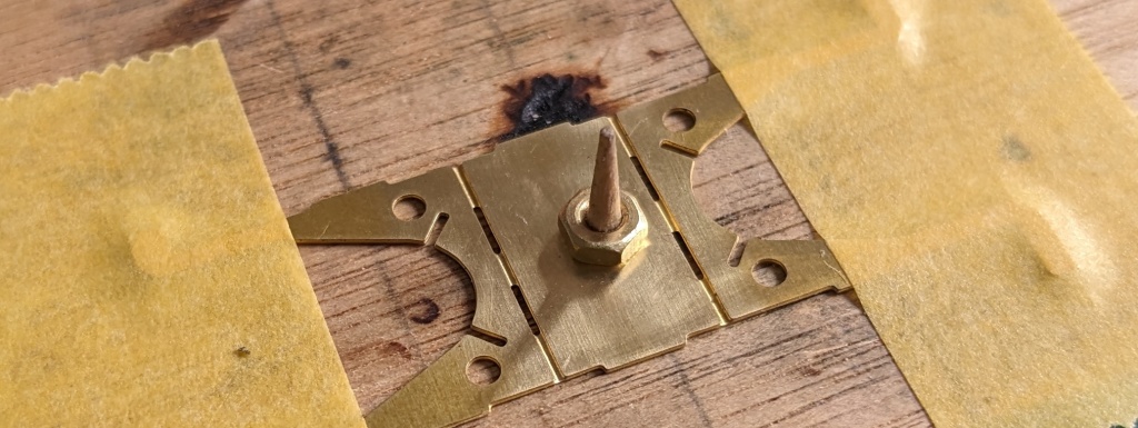
The starting point of this stage is to solder a nut to each of the bolster centre parts. The nuts need to be positioned centrally over the holes in these parts and the instructions describe how to do that by temporarily fixing them firmly in place with their corresponding bolts. The downside of this technique, as others have discovered, is the risk of soldering the bolt as well as the nut even if you take the recommended precautions! So, I opted for an abundance of caution and instead used a stub from the end of a cocktail stick and a couple of strips of masking tape to position things accurately for soldering.
Before proceeding with any bends, now is the perfect time to check that the bolts fit smoothly and squarely in the nuts. If any adjustments are needed, it’s much easier to remedy while the bolster centres are still flat and the nuts are still accessible with the soldering iron.
The next job is to prepare the bolster sides. There are two per bogie to fold up and solder so it’s a mini production line to do the same tasks four times over. Once again, the instructions are perfectly clear and accompanied by photographs and a diagram. As long as you do the folds in the order described and solder where and when indicated, this is a simple job albeit a little time consuming. Then I added the traction restraints, checking that the slots in them are a good sliding fit over the subframe ears.
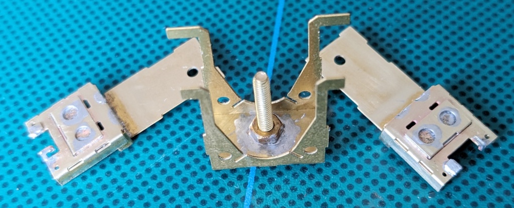
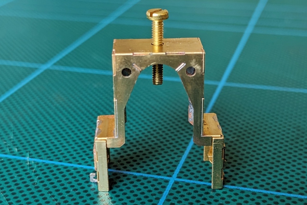
Now is the time to solder together the three sub-assemblies for each bolster. It’s definitely worth taking the time to dry fit the parts to make sure you understand how they go together before committing yourself to soldering. The kit is cleverly designed with slots and tabs to accurately position everything. So you should know when you’ve got things arranged correctly because everything will neatly look and feel right.
The fun bit is keeping everything in place for actual soldering. Frankly, only having two hands, I find this impossible without a little assistance! But my solution was pretty simple: I just used some tightly applied masking tape to keep everything held together firmly so that I could apply flux and tiny chips of solder where needed. Then it was a much easier task to zap each joint with the hot iron.
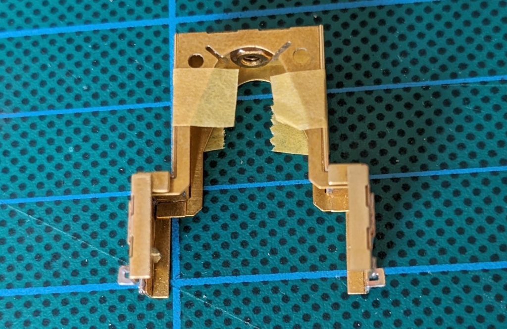
The final step was to add the two stiffeners to each bolster. At this stage, I could also have done the work to add the two top planks but I have opted to leave that until later once I’ve been able to confirm that everything works electrically and mechanically. I finished up this session by test fitting the bolsters on their corresponding subframes to ensure a good smooth fit. I was pleasantly surprised that everything was just perfect without any need for fettling.
Hopefully I will have the second kit soon and be able to use it for spare parts to complete the subframes. If not, the next session will probably see me discuss and test assemble the wheels.
