Deep breath, here we go, time to begin building the Penbits sprung bogies for my Bachmann Class 25/1 conversion.

The learning curve I have been on with Rumney Models underframe kits has boosted my confidence and experience with photo-etched brass and soldering techniques. This has played a significant part in me feeling ready to take on the challenge of building a Penbits sprung bogies kit. So here we go!
The first thing I want to say is that Ian Penberth of Penbits and Justin Newitt of Rumney Models must be brothers separated at birth. The attention to detail and quality of their products have a huge amount in common. Perhaps the most obvious parallel is that both provide highly detailed, clear and tip-laden instructions on their respective websites. Don’t be put off by confusing the length of the Penbits instructions with complexity – if you take things a step at a time, it should all be straightforward.
The instructions are split into ten distinct parts (almost like chapters of a book) and each one comes with a checklist so that you can ensure you’ve completed it successfully. My plan is to split my project build of the bogies so that it follows these ten parts and pause for a break between each one. You can read the instructions for each part yourself so I’ll only go into detail where I want to explain my techniques, where I deviate from the instructions or where I encounter challenges.
The opening part covers the bearing carriers and the first job is to check that the supplied brass bearings run smoothly in the subframe axle slots. While you’re at it, now is a good time to check that the axles will rotate smoothly in these bearings and that the bearings fit neatly in the holes etched for them in their carriers. I found I needed to do a little gentle fettling with a fine round needle file to get things just so.
Once you’re happy with that, the main task is to fold up the bearing carriers, strengthening them with solder as and when indicated in the instructions. One important thing to remember is that each set of four bearing carriers is held within its own frame and you should not remove them from those frames at this stage. Another important thing to note is that the various parts are marked/not-marked with small triangles and dots. This so that you can keep the parts for each bogie together (the triangles) and pair each bearing with an individual axle slot (the dots).

I used my invaluable “hold and fold” tool along with a steel ruler to help make the folds as easy and neat as possible but you can use a vice instead. With the initial folds done, it’s time to solder the bearings to the carriers. The instructions provide very clear guidance for how to use double-sided tape on a flat heat-proof surface to accurately position and hold the bearings and carriers in place for soldering. I can do no better than recommend that you read them several times to become familiar with them and subsequently follow them to the letter. They’re not difficult – especially if you follow the tip about using a permanent marker to mask places where you don’t want solder to stray.
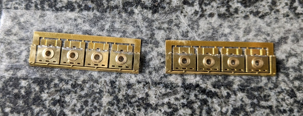
The next job was some clean up to remove any excess flux, solder and stickiness from the double-sided tape (isopropyl alcohol is good for the latter). Then it was time to remove the individual bearing carriers from their frames and make the final folds. The instructions tell you to strengthen some of these folds with a fillet of solder which seems sensible to me given that these parts will bear the weight of the locomotive.
The final step is to test fit each bearing carrier in its respective subframe axle slot. Remember, the triangle and dot marks I mentioned earlier are your guide to pairing each bearing carrier with its correct slot.

This is the point where I found out that some of the bearing carriers didn’t slide as smoothly in their slots as I would like. In some cases, this was because I hadn’t quite got several of the bearings appropriately positioned in their carriers. So I had to do a bit of tweaking by placing the parts back on the flat heat proof surface and zapping them with a hot soldering iron again while applying pressure with a pair of tweezers to correct the alignment. In the event, the solution was quite simple and I definitely learnt what to look out for in future. Another thing I discovered was that the ears at the top of the bearing carriers sometimes foul smooth movement if they haven’t been fully folded through 90 degrees or if they have a rogue spot of solder on their outside faces.
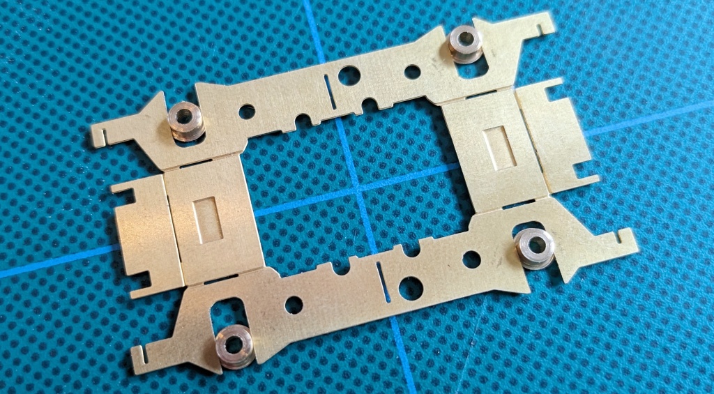
I have definitely learnt some useful lessons from this first part of the project and, looking back, some of my soldering could have been a bit neater. Overall though, I’m pretty pleased and I’m looking forward to the next part which involves folding up and soldering together the subframes.
