Here’s how I set about construction of my own accurate couplings from some photo-etched brass parts and a length of brass rod with the aid of a home-made tool.
We modellers often put extreme effort into building accurate rolling stock models, so it seems a shame to spoil the effect by not devoting the same care and attention to couplings. I know some people find scale couplings fiddly to use but, for me, getting them right is one of the essential finishing touches. The trouble is that there don’t seem to be many, if any, convincingly accurate and affordable couplings on the market. But all is not lost – certainly not when it comes to Instanter and three link couplings!
Before going any further, I want to give credit where it’s due. My approach to building realistic working couplings follows the example set by the late John Hayes. Hayes was a superlative modeller and his wagon modelling articles in Model Railway Journal remain a constant source of inspiration for me. If you’re interested in finescale wagon modelling, then Hayes’ book The 4mm Coal Wagon: A Step-by-Step Guide (Wild Swan, 1999) should definitely grace your shelf. Towards the end of that book, Hayes describes how he built his own three link couplings and, with typical attention to detail, the tool he devised as an aid to creating links to a consistently high standard.
The basis of Hayes’ tool was a short length of 3.5mm wide x 1mm thick brass strip. Nowadays, there seems to be no readily available supply of brass strip pre-cut to these dimensions and, to be frank, I couldn’t be bothered to cut my own! But necessity is the mother of invention and, in this case, I think I have come up with an improved version of the tool. My eureka moment came when I discovered that the Albion Alloys range (available to buy from a variety of retailers – I used Scale Model Shop) includes 1mm x 1mm square brass rod (Cat. No. SBW 10) and 1mm x 2.5mm ‘C’ channel (Cat. No. CC2) lengths. I realised that I could solder together equal lengths of these two products to produce something with the same dimensions as the original Hayes tool but with the added benefit of the recessed ‘C’ channel being handy when cutting the links later in the production process.
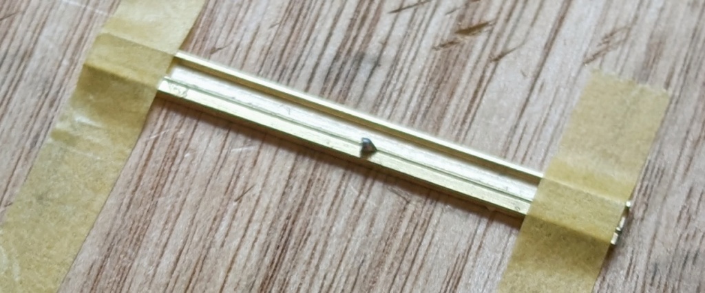
You only need a short tool for the job, so I cut 40mm lengths of both the ‘C’ section and square rod because that size would fit neatly into my hand-held vice. I cleaned the two surfaces to be soldered together with a fibreglass brush and applied LaCo flux to them. To get the two lengths of brass perfectly aligned, I placed them together on a flat surface and secured them firmly in place using some masking tape (see Figure 2). One of the arms of the ‘C’ section seems to be slightly narrower than the other, so that’s the side I chose to solder to the square rod. Next I brushed some more flux along the joint and put some chips of solder in place. Then it was a simple job to apply the hot soldering iron and watch with satisfaction as the solder flashed along the joint. Then I turned the parts up the other way and repeated the same steps to ensure a strong bond. You may need to add a bit more flux and solder to fill the gaps where the parts were held down with masking tape.
A couple of small refinements were needed to complete the tool. I rounded off each of the four edges with a file and drilled a 0.45mm diameter hole through the ‘C’ section at one end of the tool. With the tool preparation complete, I was able to start using it to make my own links from a length of 0.45mm diameter brass rod. I used to source all my brass rod from the late lamented Eileen’s Emporium and, thankfully, Cambrian Model Rail has picked up the baton now.
Here’s a step-by-step description of what to do:
- Make a short 90-degree bend close to one end of the rod so that it forms an ‘L’ shape.
- Thread the rod through the hole in one end of the tool until it catches on the ‘L’ bend.
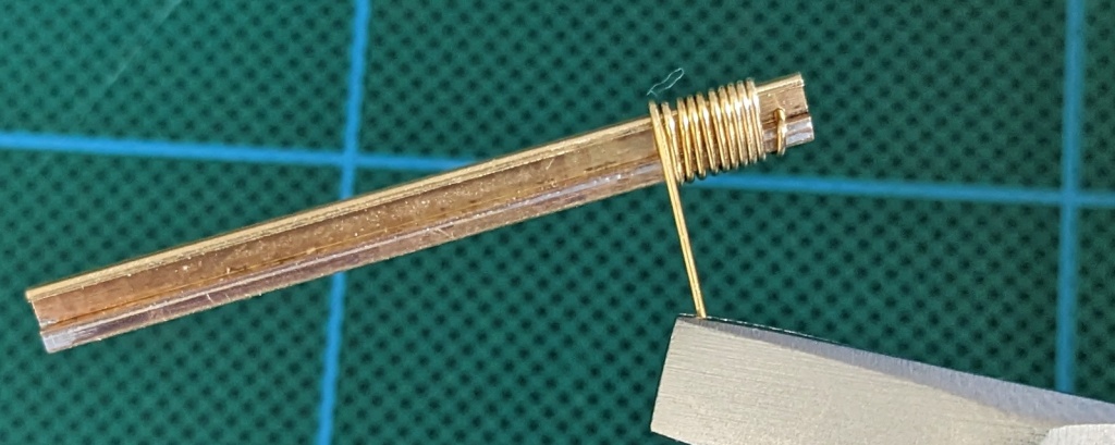
- Now you can grip the bent part of the rod firmly against the tool (either with your fingers or a pair of pliers but I find the ‘L’ grips well enough by itself) and start to wind the rod tightly around the tool. You might be able to do this by gripping the rod between your fingers or you may prefer to use a pair of pliers.
- Keep winding until you have sufficient loops to make all the links you need. You may as well do a job lot in one go (see Figure 3).
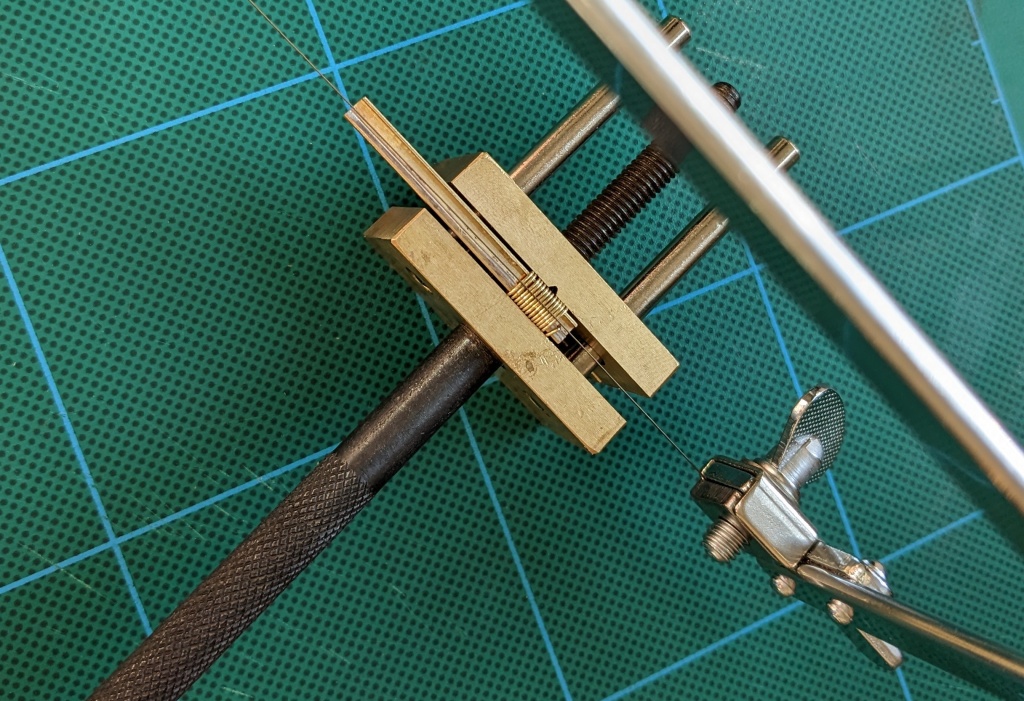
- Secure the wound rod and tool in a vice with the ‘C’ channel of the tool facing upwards.
- Cut along the loops using a fine blade in a piercing saw. Go gently so that you avoid distorting the loops too much. When you’ve finished, you’ll have a nice pile of links to hoop together to form couplings.
Hopefully the accompanying photographs will make the above steps clear.
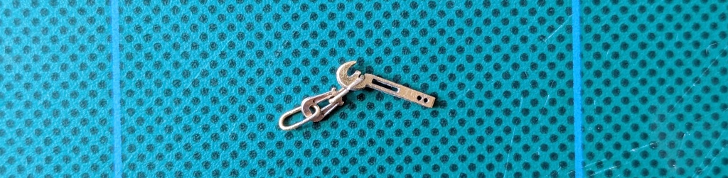
Most of the wagons I model were fitted with Instanter couplings, so I’ll describe the assembly steps for those next (but the process is analogous for good old fashioned three link couplings).
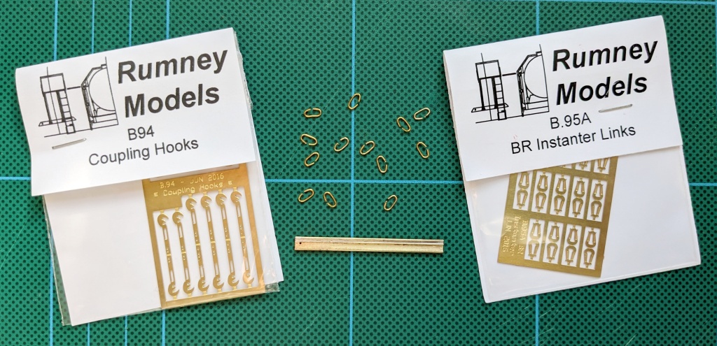
I use BR Instanter links (Cat. No. B.95A) and coupling hooks (Cat. No. B.94) from Rumney Models. Both of these components are etched in such a way that a pair of connected identical pieces need to be folded over and soldered together to form a double-thickness laminated part. Before I remove the etches from the fret and fold them, I flux and tin the inside surface that will be the soldered together to form the laminate. I do this by painting a swipe of La-Co flux on the part and then using the hot soldering iron to thinly coat the surface with solder. Then the parts can be removed from the fret, fluxed again, carefully aligned and folded through 180-degrees before simply using soldering iron to melt the solder and create the joint.
Now is a good time to do any clean up to remove excess solder and tarnish from the brass surfaces. While I’m at it, I also file the coupling hook a bit to give the impression of a cast rounded hook rather than an etched flat one.
The next job is to thread on two of the 0.45mm diameter brass rod links I made earlier and close up the joints gently with a small pair of pliers or a pair of tweezers. I find a bit of rolling on a flat surface with a tiny flat file helps make things tidy. If you’re happy at this point, you could easily stop here and call the job done. But I like to go a bit further to disguise the cut joint in the links. So I apply some flux to the joints and add a bit of solder to them to fill in the gaps. One tip to make this job a bit easier is that it’s handy to mount the links joint side up on one limb of a pair of tweezers. The solder doesn’t tend to form a bond with the steel so it’s easy to slide the link off when you’ve finished. Afterwards you can remove the excess solder with a small file and a fibreglass brush.
And that’s it! Depending on how you mount your couplings to your wagons and your approach to painting, you may wish to chemically blacken the finished coupling before fitting it to your wagon. Just remember that chemically blackened brass isn’t soldering friendly so if you plan to solder your coupling in place, leave the joint area unblackened.
The only niggling doubt in my mind is that I’ve seen scans of 1923 RCH drawings that show the thickness of the chains in three-link couplings as 1.5 inches (i.e. a scale 0.5mm) so I’m wondering if I should switch from 0.45mm to 0.5mm diameter brass rod. There must have been a reason why Hayes opted for the slightly thinner links, so I think I’ll follow the maestro’s lead until I have a good reason not to.
