With the basic structure in place, the next step is to add springing to the underframe so that it can roll along smoothly on its wheels.
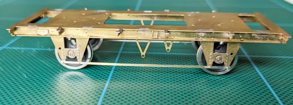
One of the main reasons I opt to replace the underframes on plastic kits with photo-etched brass ones from Rumney Models is that they provide an accurate, relatively stress-free route to a fully sprung wagon without the hassle and guesswork of butchering and fettling plastic parts to make room for metal axleguards. Yes, Rumney Models kits require some additional skills (which were my ambition to learn anyway) and call for patience but the outcome is well worth the investment – especially for Scalefour modellers. And this is certainly true of the running qualities of the underframe when combined with Exactoscale axles, wheels and bearings.
Only a few parts need to be added at this stage to get the sprung underframe operational for test purposes. I started with the tiebars because these are needed to retain the spring carriers in place. These parts are notoriously easy to damage, so the addition of some strengthening is the wise thing to do while they are still safely attached to the fret. On more recent kits, Justin Newitt has etched slots in the rear of the tiebars to accept lengths of 0.3mm diameter brass rod. Even though the older kits don’t have this innovation, the principle is still the same – you just have to work a little harder to position the lengths of rod in place before you solder them.
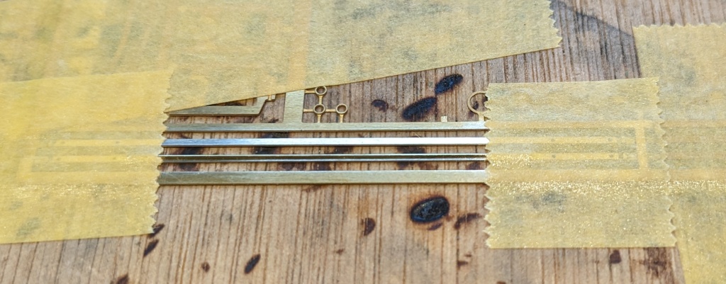
To achieve this, I first cut two 40mm lengths of 0.3mm diameter brass rod. Then I fixed the fret containing the tiebars outer face down to a small flat plywood offcut with masking tape. Next I cleaned up the tiebars with my fibreglass brush and temporarily secured the rods in position with small pieces of tape at each end. Then I brushed La-Co flux along the joints, added a small nugget of flux in the middle and introduced the hot soldering iron. If you get it right, the solder will melt quickly and flash along the length of the rod. You may need to encourage the flow a little with the iron or add a little more flux and solder. Once that is done, you can remove the tape from the ends of the rods before adding more flux and heat to get the solder to flow the full length of the rods.
It was at this point that I realised it would have been better to secure the fret to some cork sheet because the next step calls for drilling through the four holes in each tiebar into the wood below with a 0.3mm diameter drill bit. Cork is more forgiving than plywood and that reduces the chances of snapping the drill bit. So I made the switch and then inserted short lengths of 0.3mm diameter brass rod into all eight holes, fluxed the joints and soldered each one with the tiniest amount of solder.
With all that work done, it was time to remove the tiebars from the fret, clean them up ready to trim/file back the rods on the outer sides to represent bolt heads. It’s at this point that I discovered that the tiny rods were a little out of alignment or perhaps the soldered joint was weak in one case. When that happens there’s nothing for it except a steady hand and a bit of tweaking with the aid of a hot iron and a pair of tweezers. Somewhat frustrating!
Since describing the above approach to fitting the pins to the tiebars, I’ve been mulling over whether there is a less fiddly method that can produce consistently better results. The good news is that I think I have devised one! The bad news is that I don’t have time to explain it now but I will write up the technique the next time I do it.
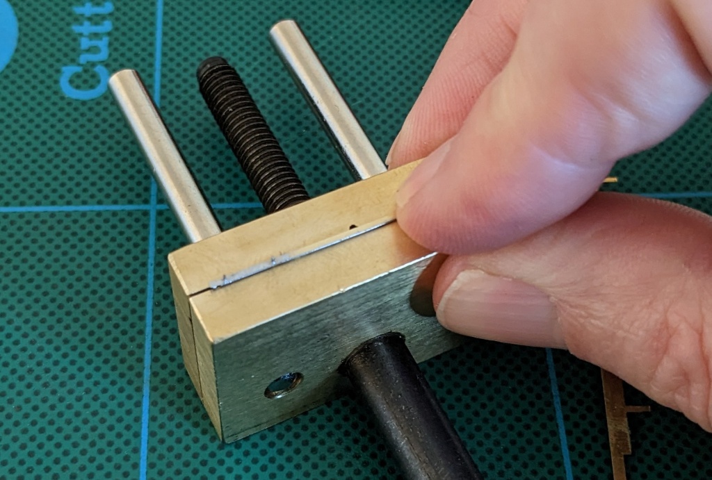
The parts are stronger now but not impervious to damage, so I fixed them in a tiny hand-held vice I got from Squires Tools to make the work easier. When all was done, I test fitted them to the axleguards and bent the ends through 90 degrees.
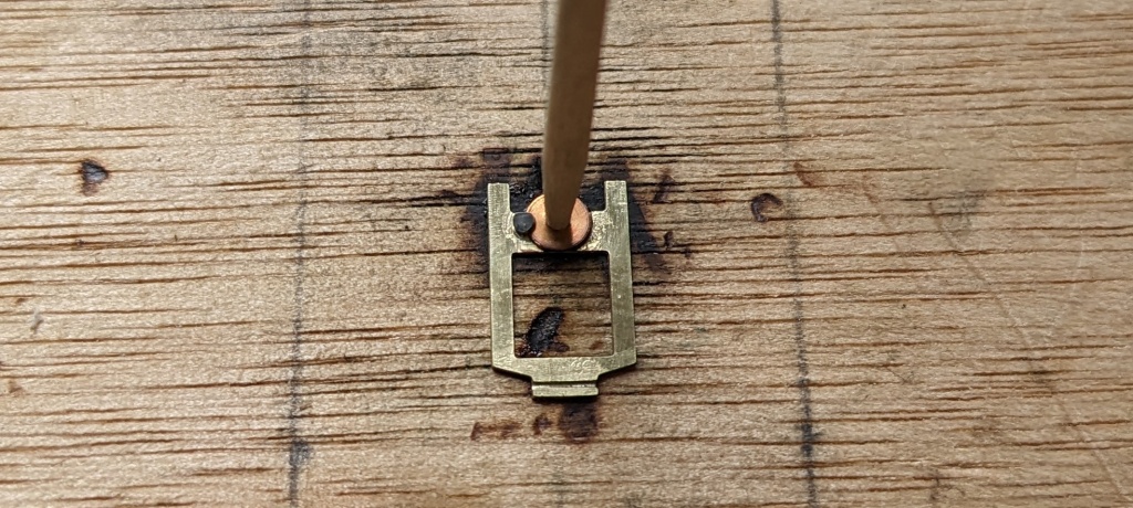
The next task was to prepare the four spring carriers. Each one needs to have a bearing soldered into position in the hole provided. I use Exactoscale parallel bearings, so I clean and flux the recessed perimeter around the hole in the spring carrier, put the bearing in place with both parts over a 2mm diameter hole in a piece of wood and hold it there with a cocktail stick. Then I add a chip of solder and wield the hot iron.
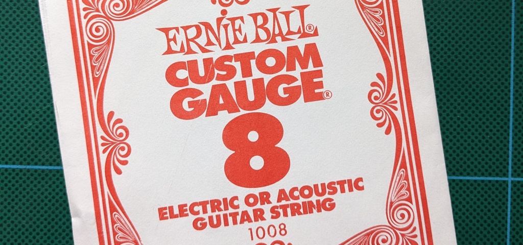
What is a spring carrier without a spring to carry? If you bought your underframe kit new from Rumney Models, you’ll see that it includes a length of steel wire for you to cut to size for the springs. In my case, I acquired this underframe kit at a bargain price from the “bring and buy” stand at last year’s ScaleForum exhibition (apologies to Justin but he does get plenty of business direct from me!). The downside of this was that the springing wire was missing. So if you ever find yourself in this embarrassing situation, it’s handy to know that an appropriate source for this wire is Ernie Ball 0.008-inch steel guitar string. Just one string will probably last you for years!
You need a spring length of about 20mm soldered in position centrally in the groove on the rear of each spring carrier. I fluxed the area liberally, pre-positioned the steel wire in the groove, added the traditional chip of solder and introduced the iron while pressing the wire in place with a wooden coffee stirring stick. It’s amazing how handy the flat side of these little things can be! One of the great things about the Ernie Ball steel guitar strings is that they are tin-plated which makes them much easier to solder in place.
The purpose of the tiny washers provided on the fret is to prevent lateral slop of the wheels. So this is a time for a bit of test fitting the wheels and spring carriers in place with some washers to get the right number for a good tight fit. The washers are best placed over the bearings on the outside face of the spring carriers and, ideally, you want the same number/thickness of washers on each spring carrier. Sometimes there aren’t the right number and thickness of washers on the fret, so I steal some from other kits (I have a couple of abandoned failures in the spares box!).
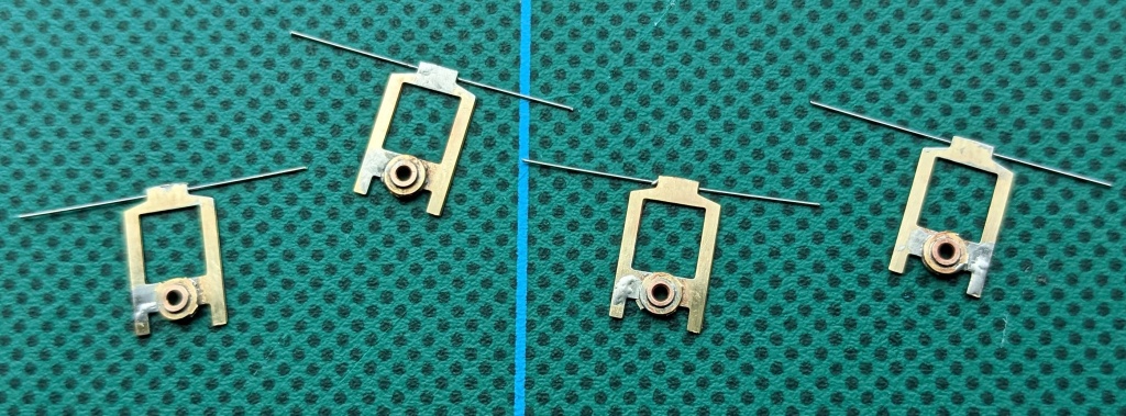
Once I’d finished experimenting to get the right washer configuration, I soldered them in place over the bearings. There’s no need to fit one washer at a time. Just put all the washers on each bearing in one go and, if you flux them sufficiently, you can solder them in one hit. The observant among you will have noticed that I skipped over assembly of the Exactoscale wheels and axles. The reason being that this is a task needed for every wagon building project, so I plan to do a dedicated posting about the tools and techniques I use so that I can simply link to it from all future projects.
So this marks a good point to pause with the picture at the top of this posting that shows the progress so far. In the next installment, I’ll move on to the brakegear.
